

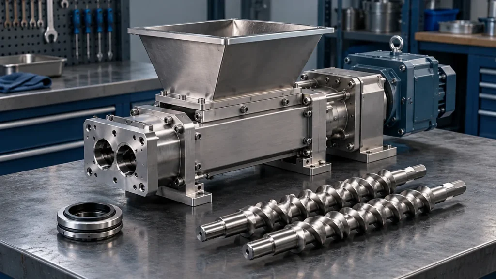
Twin screw side-feeder maintenance should cover the material-contact screws, powder seals, transmission and connection to the main process section. Cleaning the hopper alone leaves much of the assembly outside the service scope.
A side feeder, often called a side stuffer, introduces material into a downstream location on a compounding extruder. It may receive material from a separate metering feeder. Maintain those devices as distinct assets: servicing the side feeder does not automatically calibrate the upstream loss-in-weight feeder.
Identify the installed arrangement
Record the side feeder’s model, serial number, screw configuration and connection location. Identify the actual gearbox arrangement, seal design and any approved air-management or venting features.
The materials matter. Mineral filler, pigment, glass fiber and other additives can create different cleaning, abrasion and handling requirements. Use the material safety information and the equipment instructions when defining the task.
For an established line, keep the installation drawing with the maintenance package. For a new masterbatch or filler-compounding project, include access for cleaning and side-feeder withdrawal in the layout review.
Separate three maintenance boundaries
The first boundary is the metering system that supplies material. Its weighing, refill and calibration tasks belong to that unit’s instructions.
The second is the side feeder itself: hopper or inlet, screws, housing, seals and drive. The third is the interface with the main extruder, including the mounting and any installed venting arrangement.
This separation makes a work order more precise. It also prevents a feeder-instability complaint from being answered by replacing unrelated side-feeder components. The existing unstable-feeding diagnostic guide covers the evidence needed when delivery is irregular.
Plan cleaning around material carryover and access
Define which material-contact surfaces need cleaning for the next formulation. Include retained powder at connections and surfaces outside the visible hopper. Physical cleaning, opening covers or withdrawing screws requires the specified isolated state.
Use the approved cleaning method for the material and component finish. Uncontrolled compressed-air cleaning can spread dust and contamination; it should not be treated as the default method. Some materials also require particular exposure controls or equipment precautions.
Where screw removal is part of the task, preserve identity and orientation. Protect the parts from damage and avoid mixing assemblies from different feeders.
| Service area | Question to resolve | Record to retain |
|---|---|---|
| Hopper and inlet | Is the old material removed from the defined contact surfaces? | Cleaning scope and material transition |
| Screws and housing | Are deposits or condition concerns present? | Identified observations and inspection findings |
| Powder seals | Does the installed design show deterioration or leakage? | Seal reference, location and assessment |
| Transmission | What lubrication and service instructions apply? | Gearbox identification and service history |
| Main-extruder connection | Has the approved mounting arrangement been restored? | Assembly checks and drawing reference |
Assess seals and transmission as separate systems
A powder seal and a gearbox lubricant seal have different functions. Identify the location of any observed leakage before ordering a replacement.
Record whether the concern is powder escape, oil loss or another observation. The correct response depends on the installed design and the inspection result; a general “seal kit” description may not identify the required part.
For lubrication, follow the side-feeder gearbox instructions rather than borrowing the main extruder’s oil specification or service interval. Some units have more than one gearbox or service point. Confirm what is installed instead of assuming a single common fill.
Keep air-management features in the approved configuration
Powder feeding can involve air carried with the material. Where the installation has a venting or air-management feature, include its condition and approved cleaning scope in the plan.
Do not block an opening, modify an air connection or alter a venting arrangement as a quick response to powder escape. Changes at this interface can affect more than the local symptom and need review by the responsible supplier.
If material is found in an unexpected location, record the operating event and preserve photographs taken from approved observation points. Recent formulation, throughput or downstream changes may be relevant to the investigation.
Verify installation before assessing feeding performance
After authorized service, confirm that the correct screws, seals, guards and connections have been restored. Follow the OEM’s alignment and mounting requirements for the side feeder and main extruder interface.
Then evaluate the agreed operating case. Record the formulation, metering arrangement, side-feeder setting, relevant main-extruder conditions and product checks. A different filler or loading level should not be treated as an identical before-and-after comparison.
If an upstream weighing feeder was also serviced, keep its calibration and verification results separate. This makes it possible to distinguish mechanical side-feeder work from changes in material metering.
What should a useful maintenance handover contain?
A compact handover should identify the equipment, completed cleaning, installed replacement parts and unresolved findings. Include the instruction references and the agreed operating verification.
For recurring problems, retain the time relationship between the event, refill activity, material changes and main-extruder conditions. Replacing another component without reviewing that history can repeat the same uncertainty.
When buying or replacing auxiliary machines, ask for service access, part identification and the interface documentation as part of the supply scope. To discuss an installed unit, provide those records through the after-sales support process so the matched supplier can assess the actual assembly.