

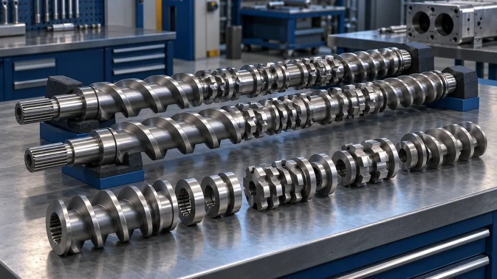
A twin screw extruder screw-removal job needs more than a shutdown date and replacement elements. The service team needs the installed screw drawing, an approved removal method, a way to preserve component identity and clear checks for returning the machine to production.
This checklist is for planning work on modular co-rotating compounding extruders. It does not replace the original equipment manufacturer’s, or OEM’s, dismantling instructions. Removal temperature, handling method, element indexing, fastener treatment and tightening requirements depend on the actual design.
Define whether the job concerns a shaft assembly or individual elements
Removing complete screw shafts from the process section is different from separating elements from a shaft. A work order that says “remove screws” can leave the necessary tools, inspection scope and service responsibility unclear.
State whether the job includes pulling assemblies, dismantling elements, cleaning, dimensional assessment, shaft inspection, replacing parts or rebuilding a configuration. Identify which tasks will be performed on site and which need a specialist workshop.
For modular assemblies, element order and orientation are part of the configuration. A collection of apparently similar conveying elements or kneading disks is not enough to reconstruct the approved arrangement. See the screw-design guide for the roles of different element types.
Before the shutdown: prepare the job package
Use the current machine and screw-assembly documents. If the installed configuration differs from the original drawing, resolve that discrepancy before dismantling it.
| Preparation item | What the service team needs |
|---|---|
| Equipment identity | Extruder model, serial number and relevant shaft/element references |
| Configuration | Approved screw sequence, positions, orientation and revision |
| Work scope | What will be cleaned, assessed, retained or replaced |
| Handling plan | Approved removal tools, support positions, lifting arrangements and access |
| Service instructions | Isolation, material condition, removal and reassembly requirements |
| Acceptance | Required inspection evidence and return-to-service checks |
Agree how removed parts will be marked and stored without damaging critical surfaces. Prepare protected supports and designated locations so assemblies do not become mixed with parts from another line.
During preparation: connect cleaning to the breakdown procedure
The cleaning job should leave the machine in the condition required by the approved service method. Purging instructions are specific to the cleaning material and process; they are not a substitute for the breakdown procedure.
A filled purge may have different restrictions from an unfilled grade. Temperature advice for one resin or cleaning product must not become a universal screw-pull temperature.
Physical work requires the authorized isolation and verification steps for the machine. The method must address hot polymer, pressure, stored energy and handling risks. An instruction that requires a warm component does not permit working on a pressurized or inadequately isolated system.
During removal: preserve identity and stop when the method no longer fits
The service team should be able to trace each assembly and element to its installed location. Maintain the agreed identification throughout cleaning, inspection and any shipment to a workshop.
If removal resistance is outside the approved method, pause for technical review. Additional force, improvised heating or striking components can turn a service job into damage. A stuck assembly may require specialized equipment and a revised work plan.
Keep observations factual. “Element could not be separated using the approved method” is useful. “The shaft is defective” requires the relevant inspection evidence.
At the bench: distinguish cleaning from condition assessment
A clean component can still be unsuitable for reuse. Conversely, discoloration alone does not establish that a part must be replaced.
The inspection package should identify the component, the feature examined, the method and the design-specific acceptance criteria. Shaft condition and element condition are related but separate questions. Where relevant, the specialist should assess features such as shaft straightness, twist or connection condition rather than only the visible screw surfaces.
Our screw and barrel wear inspection article explains how dimensional findings should be tied to positions and comparable records. Keep those reports with the assembly drawing.
Before reassembly: confirm replacement compatibility
A similar outside diameter does not prove that an element fits the installed shaft and configuration. Confirm the relevant interfaces, materials, dimensional specification, orientation and approved part references.
Record any authorized change to the assembly. Do not quietly substitute a different element sequence during a maintenance job and then compare production as though the screw design were unchanged.
Reassembly should follow the OEM’s alignment, indexing and fastening requirements. The responsible technician should document the checks appropriate to that design; a generic torque figure from another machine is not a substitute.
Before release: close the mechanical and process checks
The release package should make the completed configuration clear to the operating team. Include:
- The final assembly drawing and installed replacement-part references.
- Inspection results and the disposition of rejected or retained parts.
- Confirmation that required assembly checks were completed.
- Restoration of guards, sensors, connections and protective functions.
- The authorized startup and product-verification plan.
A successful installation is not established by rotation alone. The return-to-service method must account for the actual thermal and material state, then verify the agreed production case.
If parts will be stored rather than installed immediately, obtain the appropriate preservation, support and storage instructions. Keep the identification attached to the preserved assembly.
For sourcing, send the equipment identity, drawing revision and inspection findings with your spare-parts request. Extruder China helps coordinate supplier matching; the technical approval of a removal or reassembly method remains with the responsible equipment and service specialists.