

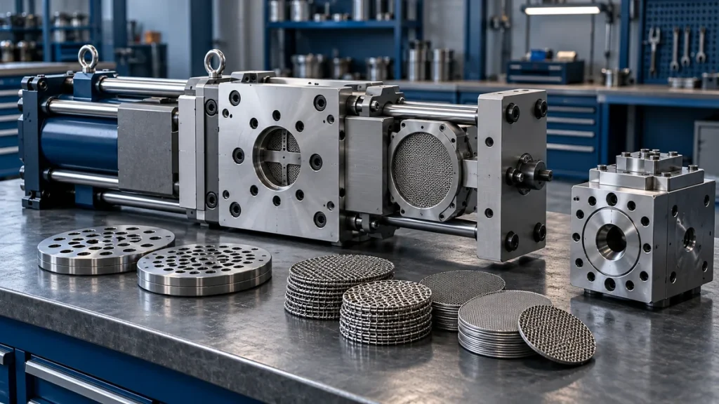
Extruder die and screen-changer maintenance should follow the installed melt-path design. The screen pack, supporting plate, moving mechanism and die are different service items, and not every twin screw compounding line uses the same arrangement.
A good maintenance plan connects the equipment identity with pressure records, material history, cleaning requirements and return-to-service checks. It should not prescribe one screen-change pressure or disassembly sequence for every line.
Identify the filtration and die arrangement first
Locate the screen changer in the process layout and identify the upstream and downstream measurement points. Note whether a melt pump or other equipment sits between the filter and die.
Record the screen-changer model, mechanism, heating arrangement and filter-media specification. Confirm whether the design is intended for interrupted or continuous screen changes. Some designs operate without additional mechanical seals, so “replace the seals” is not a universal maintenance task.
The die also needs its own identification. A strand die and an underwater-pelletizing die system have different component and service requirements. This article concerns maintenance planning for the installed assembly, not interchangeable operating instructions.
Separate screen loading from other pressure influences
Pressure information becomes useful when the measurement locations and conditions are known. Where the arrangement supports it, a pressure difference across the filter can help the team follow filtration behavior.
A change in upstream pressure alone does not prove a blocked screen. Material viscosity, temperature, throughput and other melt-path conditions may also influence it. A comparison made after changing the formulation should state that difference.
| Observation | Evidence to review | Decision that still needs confirmation |
|---|---|---|
| Pressure rises during a run | Material, output, temperature and identified pressure trends | Whether filter loading or another influence explains the change |
| Changeover performance differs | Installed screen specification and maintenance history | Whether the correct filter assembly was fitted |
| Visible leakage | Exact location, operating event and assembly history | Which interface or component requires service |
| Deposits recur after cleaning | Material route, cleaning scope and samples | Whether an unaddressed location or other condition is involved |
Use the equipment’s specified service criteria and protective limits. Do not delay necessary action because a generic internet threshold has not been reached.
Keep the screen pack and support parts identifiable
Specify the approved filter media and assembly details when ordering replacements. Apparent diameter or a single mesh description may not identify the complete required arrangement.
The relevant supporting components must also be included in the work scope. A screen replacement should not conceal an unresolved condition concern in a breaker plate or other fitted part.
Avoid changing the filtration specification simply to extend the time between changes. A different configuration can alter pressure behavior and the product’s filtration outcome. Have that decision reviewed against the process and quality requirements.
Define where production operation ends and maintenance begins
A continuous screen changer may have an approved operating sequence that maintains melt flow during a screen change. That capability does not mean every surface can be accessed or every component removed while the machine is operating.
Cleaning, dismantling and service work must use the applicable isolation, depressurization and handling procedure. Pressure, heat and the hydraulic mechanism, where fitted, need to be addressed together.
Do not loosen a connection to test whether pressure remains. Similarly, a zero indication at one point should not be used as an improvised substitute for the approved verification of a safe service state.
Clean the die without changing its functional geometry
Agree the cleaning scope and method for the actual die material and surface finish. Deposits should be removed using the approved process without damaging sealing surfaces or altering flow features.
Uncontrolled scraping, drilling or abrasive cleaning can change more than the appearance of the component. If a passage remains obstructed or a surface appears damaged, obtain an assessment rather than improvise a dimensional repair.
When a cleaning compound is involved, check its compatibility with the installed screens, clearances and tooling. Instructions that permit a particular purge through one assembly do not authorize the same treatment for a different design.
Verify the assembled melt path after service
Follow the equipment’s requirements for reassembly, installed filter identity and return to operating condition. Keep records of any authorized change rather than treating it as a routine like-for-like replacement.
The verification should address the original work scope:
- Confirm the installed screen and component references.
- Complete the specified mounting, connection and protection checks.
- Observe the approved startup and pressure behavior.
- Check the serviced interfaces using authorized observation methods.
- Assess the relevant product samples and record the release decision.
If the line uses strand pelletizing, the pellet-quality troubleshooting guide helps separate visible defects from assumed mechanical causes. Restored flow alone does not prove that every pellet-quality requirement is met.
Prepare a useful service or spare-parts request
Include the model and serial number, process-layout location, filter specification, material and operating context, exact observations and recent work. Identify whether the request concerns filter media, support parts, the mechanism, heating or the die.
For a new line, consider cleaning access and component handling when choosing auxiliary equipment. For an installed assembly, use the identification checklist on the spare-parts page to avoid ordering a visually similar component without confirmed compatibility.